





How to Test eBike Motor Hall Sensors: Step-by-Step Guide
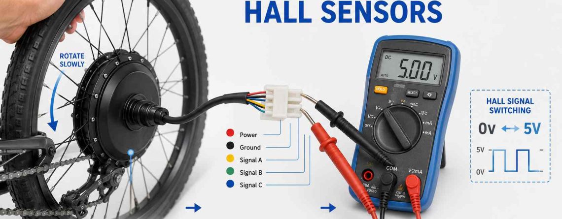
To test eBike motor Hall sensors, first verify the Hall circuit has its low-voltage supply, then measure each Hall signal while slowly rotating the motor. In a common system, each signal should repeatedly switch between a low voltage near 0V and a high voltage near the sensor supply. A signal that never switches can point to a failed sensor, damaged wire, or connection fault.
Quick Answer
- Inspect the motor cable and Hall connector before using a meter.
- Identify Hall power, ground, and the three position-signal wires from verified wiring information.
- Check for the Hall circuit’s expected low-voltage supply first.
- Measure each Hall signal while turning the motor slowly by hand.
- All three signals should switch as the rotor moves past the internal magnets.
- Do not condemn a Hall sensor until power, ground, wiring, and the connector have also been checked.
A motor that jerks, stutters, struggles to start, or refuses to run can make a failed Hall sensor look like an obvious diagnosis. But those symptoms are not unique to Hall sensors.
A damaged motor cable, loose connector, controller fault, incorrect phase/Hall combination, or another electrical problem can produce similar behavior.
The best approach is therefore to test the Hall circuit before opening the motor or replacing parts.
What Do Hall Sensors Do Inside an eBike Motor?
Motor Hall sensors tell the controller where the rotor is so it can switch current through the motor phases at the correct time.
Most sensored brushless eBike motors use several Hall-effect sensors inside the motor.
The rotor contains permanent magnets. As those magnets move past the Hall sensors, the sensors change their electrical output. The controller reads those signals to estimate rotor position.
It then uses that position information to control motor commutation.
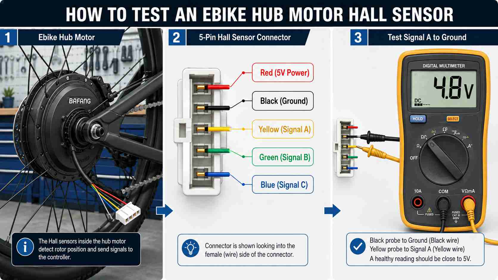
In many three-phase eBike motors, you will find three motor-position Hall signals. The Hall harness may therefore contain:
- A low-voltage sensor supply
- A ground wire
- Hall signal A
- Hall signal B
- Hall signal C
- Sometimes an additional wire for another function, such as temperature or speed sensing
Wire colors often follow familiar patterns, but they are not universal. Do not identify a wire only by its color.
Use a wiring diagram, connector pinout, controller documentation, or verified service information whenever possible.
What Are the Symptoms of a Bad eBike Motor Hall Sensor?
A failed motor Hall sensor can cause poor startup, jerking, stuttering, unusual motor noise, or loss of motor operation, but none of these symptoms proves the sensor is bad.
Possible Hall-related symptoms include:
- The motor jerks instead of starting smoothly.
- The motor vibrates or stutters at low speed.
- The motor makes an abnormal buzzing or growling sound.
- The motor starts only after the wheel is already moving.
- The controller reports a motor or Hall-related error.
- Motor behavior changes when the motor cable moves.
- The motor does not run even though the display and battery appear normal.
Do not replace the Hall sensors based on symptoms alone.
A loose phase connection can also make a motor run roughly. A damaged motor cable can interrupt a Hall signal. A controller fault can remove the Hall supply voltage. Incorrect phase and Hall wiring can also create poor commutation.
Error codes require the same caution. A number that means “Hall sensor fault” on one display may mean something different on another system.
Always use the error-code table for your actual controller and display.
Before Testing: Make the Bike Safe
Hall signal testing may require the controller to be powered, so the drive wheel must be secured and accidental motor activation must be prevented.
Start with the bike powered off.
Support the drive wheel so it cannot suddenly move the bike forward. Use a stable repair stand or another secure method. Keep hands, meter leads, clothing, and tools away from spokes, cranks, chains, and other moving parts.
Before making any powered measurement:
- Read the wiring information for your motor and controller.
- Confirm which connector contains the motor Hall wires.
- Inspect the connector for damage first.
- Keep the drive wheel off the ground.
- Do not touch the throttle or rotate the pedals while testing.
- Do not allow meter probes to bridge adjacent pins.
If your system provides a safe service procedure for disabling throttle or PAS input during diagnosis, follow that procedure.
Do not perform resistance or continuity measurements on a powered circuit. The meter’s ohms and continuity modes are intended for circuits that have been de-energized.
If you cannot safely access the Hall signals without damaging a sealed connector, stop. A service breakout cable or professional test should be used instead of forcing probes into waterproof terminals.
What Tools Do You Need to Test Motor Hall Sensors?
A digital multimeter and safe access to the Hall connector are usually enough for the basic signal test.
Useful items include:
- A digital multimeter that can measure low DC voltage
- A stable eBike stand
- The correct motor/controller wiring diagram
- Fine back-probing pins or an appropriate breakout harness
- Good lighting
- Insulated hand tools if covers must be removed to reach external connectors
You normally do not need to open the motor for the first test.
That is important. Testing at the external motor Hall connector can tell you whether the controller is supplying sensor power and whether the three Hall signals are reaching the harness.
If the external test clearly finds a missing signal, you can then decide whether the problem is in the cable, connector, or sensor before considering internal motor work.
Step 1: Identify the Hall Sensor Wires
Find the low-voltage Hall harness and identify supply, ground, and signal pins from verified information before applying meter probes.
A sensored motor often has three thick phase conductors and a group of thinner Hall wires.
The Hall wires carry low-voltage signals. A common arrangement uses five main Hall wires:
| Hall circuit function | Typical purpose |
|---|---|
| Sensor supply | Provides low-voltage power to the Hall sensors |
| Ground | Electrical reference for the Hall circuit |
| Signal A | Rotor-position signal |
| Signal B | Rotor-position signal |
| Signal C | Rotor-position signal |
You may often see red used for supply, black for ground, and yellow, green, and blue for signals.
That color pattern is common, not guaranteed.
Some motor harnesses also combine temperature, speed, or other signals in the same connector. Guessing the pinout can short a controller supply or damage a sensor.
If you do not have verified pin information, do not move directly to powered probing.
Step 2: Check the Hall Sensor Supply Voltage
Check Hall power before checking individual signals because none of the sensors can switch correctly if their supply or ground is missing.
Set the multimeter to DC voltage.
Keep the Hall connector in the normal operating configuration unless the service procedure for your system says otherwise. The controller usually needs to power the Hall circuit during this test.
Turn the bike on without commanding the motor.
Measure between the Hall supply and Hall ground.
Many eBike motor Hall circuits operate around 5V. A technical Hall test may show roughly 4–5V depending on the system and where the measurement is taken.
Do not treat one exact number as universal.
If the expected Hall supply is present, continue to the three signal wires.
If the supply is missing, stop and diagnose the supply path first. Possible causes include:
- A loose Hall connector
- A broken supply or ground conductor
- Connector corrosion
- A short in the Hall harness
- A controller low-voltage supply problem
Replacing all three Hall sensors will not solve a missing controller supply.
Step 3: Test Each Hall Signal With a Multimeter
A working Hall signal should change state repeatedly as the motor rotor turns past the internal magnets.
Keep the motor safely supported.
Place the multimeter reference probe on the verified Hall ground. Use the other probe to measure one Hall signal.
Slowly rotate the motor.
Watch the meter.
A normal digital Hall output will usually alternate between a low state near 0V and a high state near the Hall supply voltage, often close to 5V.
Stop the wheel at different rotor positions. You may see the signal sitting high at one position and low at another.
Repeat the same test for all three Hall signals.
Healthy basic pattern: Signal A switches → Signal B switches → Signal C switches as the rotor moves.
The exact switching sequence matters when configuring or matching motor phase and Hall wiring, but a basic fault test first asks a simpler question:
Does every Hall channel switch between a valid low and high state as the rotor moves?
Turn the motor slowly. If you spin it too quickly, a digital meter may average the rapidly changing signal and show an intermediate number instead of clearly displaying the high and low states.
Important: Some Geared Hub Motors Must Be Turned Backward
If a geared hub freewheels in one direction, turning the wheel that way may not rotate the internal motor rotor, so the Hall signals will not change.
This can create a false diagnosis.
You rotate the wheel. Nothing changes on the meter. It looks as though all three Hall sensors have failed.
But the freewheel may simply be allowing the wheel shell to move without turning the motor rotor.
If your hub motor uses an internal freewheel, slowly try the direction that mechanically drives the motor. On some geared hubs, this means rotating the wheel backward during the Hall test.
You may feel more resistance when the rotor is actually turning.
If you are unsure, use the service information for the motor rather than forcing the wheel.
How to Read Your Hall Sensor Test Results
The pattern across all three channels is more useful than one isolated voltage reading.
| Test result | Likely area to investigate |
|---|---|
| No Hall supply voltage | Controller supply, supply wire, ground wire, connector, or harness short |
| Supply is present and all three signals switch | Basic Hall operation is present; investigate other motor/controller causes if the fault remains |
| Two signals switch but one stays high | That Hall channel, signal wire, connector pin, or internal sensor |
| Two signals switch but one stays low | That Hall channel, shorted signal, wire, connector, or sensor |
| All signals stay unchanged | Hall supply/ground issue, wrong test point, rotor not actually turning, connector problem, or multiple Hall faults |
| Signal changes when cable is moved | Intermittent cable, connector, or conductor fault |
| Signals switch but motor still stutters | Phase wiring, Hall/phase sequence, controller, phase connection, or another motor fault |
A signal stuck high or low does not automatically prove that the Hall IC inside the motor has failed.
The wire between the sensor and connector may be open. The signal may be shorted. A pin may be pushed back inside the connector.
That is why the next step is to separate an internal sensor fault from an external harness fault.
Sensor Failure or Damaged Motor Cable?
If one Hall channel fails, inspect the complete signal path before opening the motor.
Hub-motor cables often pass close to an axle, dropout, frame, or rotating wheel. Damage in this area can interrupt a Hall conductor even when the internal sensor is healthy.
Power the system down before performing a close visual inspection.
Look for:
- Crushed cable near the axle
- Sharp bends
- Damaged insulation
- Corrosion inside connectors
- Pushed-back pins
- Loose terminals
- Evidence that the cable has rubbed against the frame or wheel
If the signal worked during part of the test but disappeared when the external cable moved, a harness fault becomes more likely.
Do not repeatedly flex a damaged motor cable while the system is powered.
An intermittent short can damage the controller’s low-voltage sensor supply.
What If All Three Hall Sensors Pass but the Motor Still Stutters?
Three switching Hall signals rule out some faults, but they do not prove the complete motor-controller system is correct.
If all Hall channels switch but the motor still jerks, buzzes, or refuses to start properly, other areas remain.
Possible causes include:
- A loose or damaged motor phase connection
- An incorrect phase/Hall combination after wiring changes
- A controller output fault
- Damage elsewhere in the motor cable
- A motor winding fault
- A mechanical motor problem
Do not turn this Hall test into uncontrolled phase-wire experimentation.
If the system worked correctly before and no wiring configuration was changed, random phase and Hall swapping is usually not a sensible first repair.
Record the original connector positions before changing anything.
For broader information about eBike motor systems, use the electric bike motor guide. This article remains limited to Hall-sensor diagnosis.
Should You Open the Motor and Replace a Hall Sensor?
Only move to internal motor repair after external testing gives strong evidence of a Hall or internal wiring fault.
Replacing a motor Hall sensor usually requires more than removing a connector.
Depending on the motor, repair can involve opening the motor case, removing internal parts, locating the failed sensor, soldering wires, securing the new sensor, checking insulation, and resealing the motor correctly.
That is outside the basic diagnostic procedure in this guide.
Stop and use qualified repair help if:
- The motor case must be opened and you do not have the correct service procedure.
- The motor cable is damaged inside the axle.
- Several Hall signals are missing even though the supply is correct.
- There is visible heat damage.
- Connectors or wiring are melted.
- The controller’s Hall supply appears damaged.
- The repair requires soldering inside a sealed motor.
A correct diagnosis before disassembly saves time. It also reduces the chance of replacing a sensor when the actual fault is in the controller or harness.
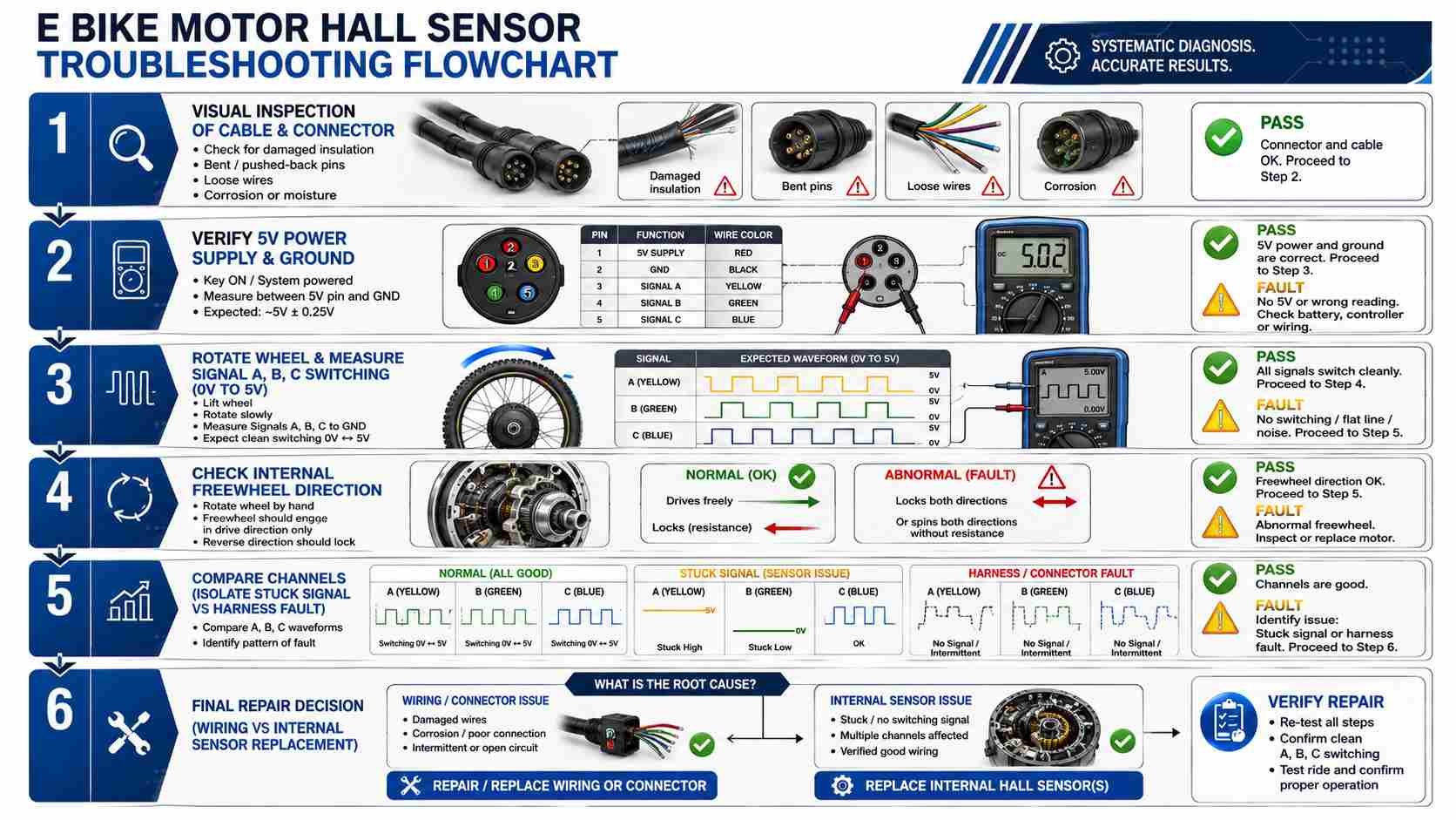
Hall Sensor Testing Checklist
Use this order to avoid replacing parts before confirming the actual fault.
- Record the symptom. Note jerking, stuttering, no start, error codes, or intermittent behavior.
- Power down and inspect. Check the motor connector and external cable.
- Secure the drive wheel. Prevent unexpected bike movement.
- Verify the pinout. Identify Hall supply, ground, and three signals from reliable information.
- Check Hall power. Verify the expected low-voltage supply.
- Measure Signal A. Turn the motor slowly and confirm switching.
- Measure Signal B. Repeat the test.
- Measure Signal C. Repeat again.
- Consider the freewheel. Make sure the rotor is actually turning.
- Compare all three results. Look for one stuck or intermittent channel.
- Inspect the harness. Separate cable and connector problems from an internal sensor fault.
- Stop before internal repair. Open the motor only with the correct procedure and skills.
Frequently Asked Questions
How do I test eBike motor Hall sensors with a multimeter?
Verify the Hall circuit power and ground first. Then measure each Hall signal relative to Hall ground while slowly rotating the motor. A working signal should switch between a low level near 0V and a high level near the sensor supply as the rotor moves.
What voltage should an eBike Hall sensor show?
Many eBike motor Hall circuits use a supply around 5V. The signal commonly switches between a low voltage near 0V and a high voltage close to that supply. Exact values can vary, so use the specifications for the controller and motor when available.
Why is one Hall sensor stuck at 5V?
A signal that remains high can come from a failed Hall sensor, an open signal path, connector damage, or another wiring problem. Confirm that the rotor is turning and inspect the complete signal path before replacing the sensor.
Why is one Hall sensor stuck at 0V?
A signal stuck low can indicate a failed sensor, a shorted signal wire, connector damage, or an internal wiring fault. Compare it with the other Hall signals and inspect the harness before opening the motor.
Why do all three Hall sensors show no change?
Check Hall power and ground first. Then confirm you are measuring the correct pins and that the motor rotor is actually turning. On a geared hub motor, the wheel may freewheel in one direction without moving the rotor.
Can bad Hall sensors make an eBike motor stutter?
Yes. Incorrect rotor-position signals can disrupt commutation and cause poor starting, jerking, or stuttering. However, damaged phase wiring, controller faults, and incorrect wiring combinations can cause similar symptoms.
Can I test Hall sensors with the battery disconnected?
A Hall sensor needs a low-voltage supply to produce its normal switching signal. The standard voltage test therefore requires a controlled Hall supply, often provided by the powered controller. Do not improvise an external supply unless you have verified circuit information and understand the wiring.
Do I need to open the hub motor to test the Hall sensors?
Usually not for the first test. Hall power and switching signals can often be checked at the external motor connector. Opening the motor should come later if external testing points to an internal sensor or wiring fault.
Final Answer
The best way to test eBike motor Hall sensors is to check the circuit in order: power first, then each signal.
Inspect the cable and connector. Verify the correct Hall pinout. Confirm the low-voltage sensor supply. Then slowly rotate the motor and check whether all three Hall signals switch between low and high states.
If one channel stays fixed while the others switch, investigate that sensor’s wiring and connector before opening the motor.
If all three signals work but the motor still stutters, move the diagnosis toward the phase wiring, controller, or another motor fault.
Keep the drive wheel secure during powered testing, avoid shorting connector pins, and stop before internal motor repair if the correct service procedure is not available.



LEAVE A COMMENT