




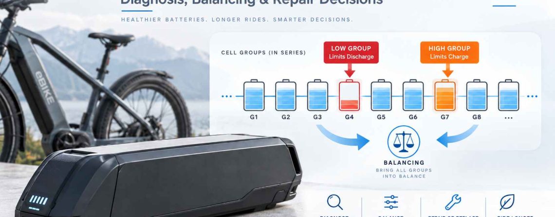
eBike Battery Cell Imbalance: Diagnosis, Balancing & Repair Decisions
eBike battery cell imbalance is a difference in state of charge between series-connected cell groups. It can restrict usable capacity when one group reaches a protection limit before the others. Voltage differences help reveal the problem, but they can also reflect resistance, temperature, measurement errors, or permanent cell degradation.
Quick answer
- Compare individual series-group readings under the same conditions. Total pack voltage can hide a weak group.
- Distinguish charge imbalance from capacity loss, excessive resistance, and unwanted current drain before choosing a repair.
- Small passive balancing currents can correct some charge differences, but cannot repair damaged cells or faulty sensing circuits.
- Use the manufacturer’s balancing procedure. Persistent drift needs professional diagnosis, not indefinite charging.
Consider a diagnostic scenario: a rider charges the battery, sees a full display, and loses assistance on the first sustained climb. Back in the workshop, pack voltage looks plausible. Replacing the charger or resetting the BMS might change nothing because neither action identifies which series group reached its limit.
From a pack-engineering perspective, the useful question is not simply, “How large is the voltage gap?” It is, “When does the gap appear, which group leads it, and does it return after correction?”
This guide focuses on those distinctions. Internal measurements and cell-group intervention belong to qualified pack-service personnel using the manufacturer’s procedure; they are not an invitation to open a sealed pack or bypass protection.
What Causes eBike Battery Cell Imbalance?
Group mismatch can originate in manufacturing variation, uneven aging, unwanted electrical drain, or cell damage. A voltage snapshot alone cannot tell these causes apart.
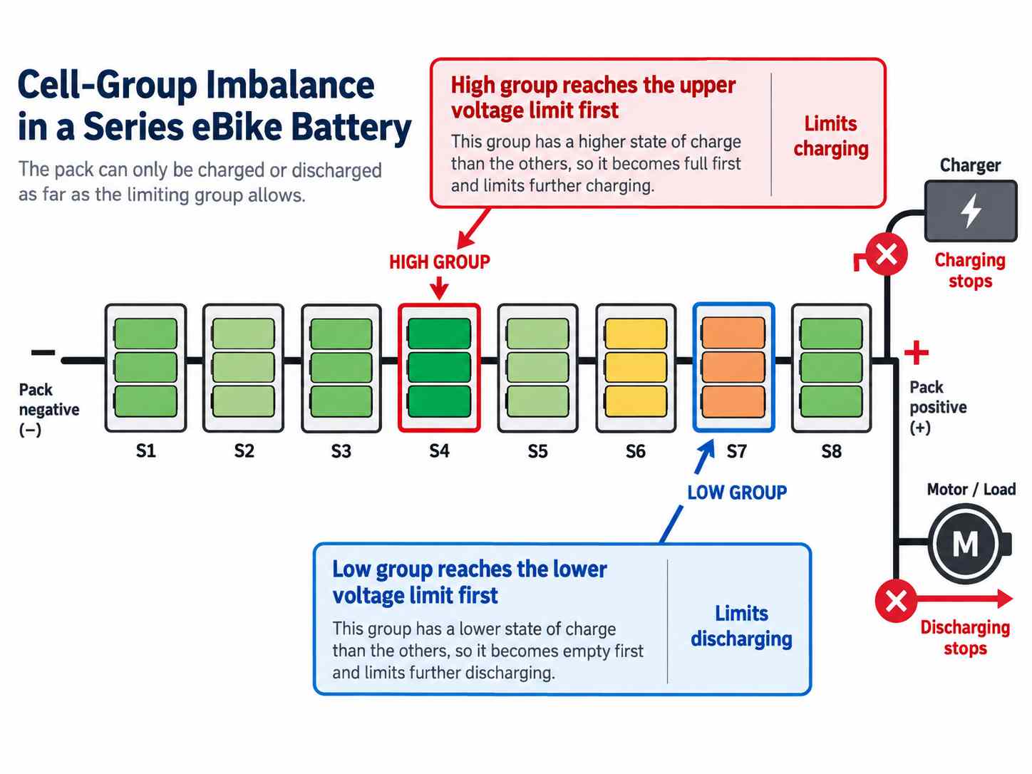
In a typical 13S 48V or 14S 52V pack, each series position may contain several cells connected in parallel. The BMS generally sees the voltage of each parallel group, not the condition of every individual cell within it.
The group reaching undervoltage protection first can end discharge while other groups retain charge. During charging, the first group reaching overvoltage protection can interrupt charging before the rest are full. These are group-level limits; a controller’s whole-pack cutoff is a separate constraint.
Initial capacity and internal-resistance variation
Matching open-circuit voltage does not establish matched capacity or internal resistance (IR). Two groups can start at similar voltage yet behave differently as charge passes through them.
A lower-capacity group reaches the ends of its usable range sooner. A higher-resistance group shows a greater voltage drop under discharge load and a larger rise during charging. A poor weld or resistive interconnect can imitate cell resistance, so diagnosis must include the current path.
Factory sorting therefore needs more than a voltage check. Cell identity, lot traceability, capacity, resistance measured under consistent conditions, and abnormal self-discharge all matter when assembling comparable parallel groups.
Local heat creates unequal aging
Cells do not necessarily share the same thermal history. A group beside a hot controller mounting area, a concentrated BMS MOSFET heat source, or a poorly cooled interior pocket may age differently from the rest.
Persistent local heating can accelerate capacity loss and resistance growth. Position is a clue, not proof: a technician should compare a physical group map with temperature and electrical behavior. Rebalancing may briefly align voltages while leaving the thermal cause untouched.
BMS leakage and parasitic drain
A leaky component, contaminated sense circuitry, or a balancing switch stuck on can draw unequal current from the stack. A group may then drift down while the bicycle is unused. Ordinary whole-pack standby consumption is different from a fault loading one group disproportionately.
Do not diagnose this from the BMS price. The evidence is abnormal channel behavior or unwanted current established through a qualified service test. A damaged sense connection can also report a false high or low voltage without actually draining the group.
Abnormal self-discharge and internal micro-shorts
A defective cell within a parallel group can draw energy from its neighbors. This means a group-level reading may expose a problem without identifying the individual faulty cell.
If a group continues to lose charge after external leakage has been excluded through an approved service procedure, internal self-discharge becomes a serious concern. A micro-short is one possible cause, not a diagnosis that an app screenshot can establish. Suspected internal damage is a reason to stop charging attempts.Can a newly built pack become unbalanced?Yes. Initial matching, a defective cell, interconnect quality, and electronics faults can matter before substantial aging occurs.Does a low group automatically mean a bad cell?No. First distinguish real charge loss from measurement error, group-specific drain, and voltage drop under load.
Read Voltage Spread in Context, Not as a Verdict
A useful voltage spread compares valid group readings at a defined state of charge, temperature, load, and rest condition. It is a screening measurement, not a universal health certificate.
Define the spread as ΔV = highest group voltage − lowest group voltage. Record the group identities as well as the difference. The same group repeatedly reaching a limit is more informative than an isolated maximum spread.
The ranges below are illustrative workshop triage bands for conventional lithium-ion eBike packs, not industry acceptance limits. Near the top of charge, after the specified rest period and with balancing inactive, they can organize further checks. Instrument uncertainty must be smaller than the difference being interpreted.
| Observed spread | Possible interpretation | Appropriate response |
|---|---|---|
| Below roughly 20–30 mV | A small spread under the stated conditions; not proof of matched capacity. | Check whether the group behavior remains consistent during approved load testing. |
| Roughly 30–100 mV | A difference worth tracking; may reflect charge mismatch or measurement conditions. | Verify readings and compare repeat observations before proposing correction. |
| Above 100 mV (0.1 V) | Prioritize investigation when persistent in comparable resting measurements. | Identify the cause; do not infer that manual charging or replacement is automatically required. |
A group that drops sharply under load and rebounds afterward points toward resistance-related behavior. A group that loses voltage during comparable rest periods suggests charge loss or leakage. A lower-capacity group may match at the top yet reach the discharge limit early. Each pattern needs confirmation.
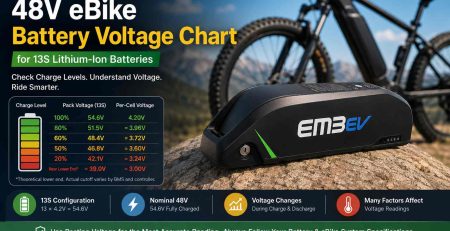
For conventional 4.2V-per-group cells, a 13S pack’s full-charge reference is 54.6V. That sum does not establish any group’s actual condition. Use 48V battery voltage chart for pack-level context; obtain individual-group cutoff limits from the actual BMS settings.
Is 0.1V always dangerous?
No. Absolute group voltage, measurement conditions, persistence, and the fault mechanism matter. A group outside its permitted limits is urgent regardless of the spread.
Can every group look equal while capacity is poor?
Yes. Similar resting voltages do not demonstrate equal capacity or acceptable resistance under load.
A repeatable engineering verification workflow
- Validate the information. Confirm cell chemistry, series configuration, approved charger, BMS thresholds, balancing conditions, and the accuracy of available diagnostic readings.
- Capture a comparable baseline. Record each group, pack current, temperature, balancing status, charge state, and elapsed rest time. Avoid comparing a charging snapshot with a resting one.
- Resolve questionable readings. Qualified technicians can cross-check group voltages through documented balance-lead test points using approved service adapters. Unexpected readings require sense-path investigation before cell intervention.
- Separate the mechanisms. Use approved, bounded load observations to assess sag; use repeat resting observations to assess drift. Professional testing must distinguish electronics drain from cell self-discharge.
- Verify the result. A successful correction must remain stable and provide acceptable capacity and load performance. A briefly smaller voltage spread is insufficient.
For external measurement fundamentals: how to test battery pins with a multimeter. That guide covers accessible external terminals, not internal balance-connector pinouts. Never assume a connector’s wiring order or use sensing leads as a general-purpose charging connection.
Why Passive Balancing Can Be Too Slow
Passive balancing is limited by charge mismatch, effective bypass current, and operating time. A voltage gap measured in millivolts does not directly tell you how long correction will take.
Some low-current passive systems bypass only around 30–60mA from selected higher groups. Other designs provide substantially more. The actual figure depends on the circuit and operating conditions; it is not a specification shared by all traditional BMS units.
An idealized estimate is balancing time ≈ charge difference ÷ effective balancing current. For example, a hypothetical 500mAh mismatch with continuous 50mA balancing would require about 10 hours of active balancing. This arithmetic is not a recommended charger connection time.
Real elapsed time can be longer because balancing may pause for temperature, voltage conditions, measurement intervals, or channel scheduling. The charger may terminate before sufficient balancing occurs. Meanwhile, a leakage fault can keep removing charge from the affected group.
A spread of several hundred millivolts therefore warrants diagnosis, but does not prove passive correction is physically impossible. You cannot reliably convert that spread into missing amp-hours without knowing chemistry, state of charge, and group condition.
Top balancing is not trickle charging
Top balancing aligns groups near the upper end of their charge range. It is not continuous trickle charging, and it is not cell “self-healing.” Lithium-ion charging must terminate or transition according to the approved charging system.
A manufacturer-approved balancing charge may help when the cells remain serviceable, the issue is charge offset, balancing actually activates, and no abnormal drain is present. Follow the specified duration and supervision requirements. Do not improvise an overnight or multi-day charging routine.Does leaving the charger connected guarantee balancing?No. The BMS may not meet its activation conditions, and the charger may not support the required operating sequence.Will a higher-current charger speed up balancing?Not necessarily. Pack charging current and the BMS’s bypass current are different limits. Increasing charger current can make a high group reach its limit sooner.
Choose Between Balancing, Internal Service, and Retirement
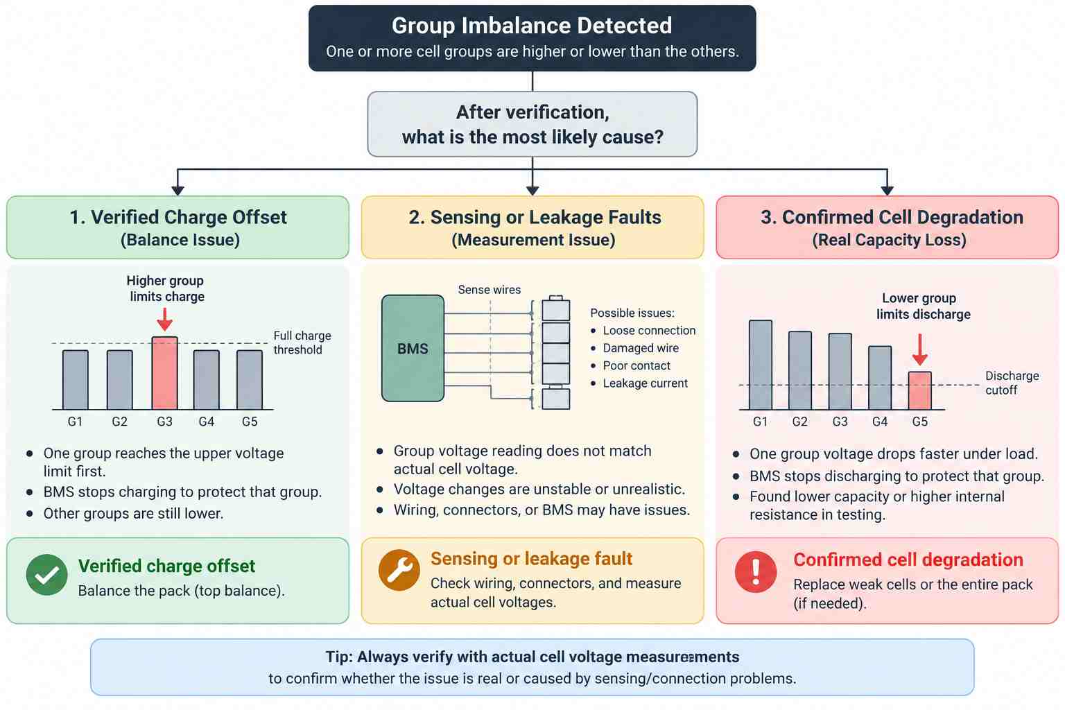
Use documented balancing for a correctable charge offset, professional internal service for unresolved faults, and retirement or an approved rebuild when cell damage or persistent degradation is confirmed.
Repair decision checklist
- Stable charge offset, no fault evidence: use the manufacturer’s approved balancing procedure, then verify retention and performance.
- Unreliable or implausible readings: diagnose the sense harness and electronics before attempting to equalize groups.
- Persistent genuine mismatch: obtain a professional service assessment; internal access may be necessary if approved diagnostics cannot identify the cause.
- Recurring self-discharge, unacceptable capacity, or excessive resistance: evaluate an approved rebuild or replacement rather than repeating balancing.
- Suspected internal short, swelling, abnormal heat, or serious damage: stop use and charging; arrange qualified handling and disposal advice.
When selective group correction belongs in a workshop
Opening a pack is not automatically the next step above a particular voltage spread. A sealed or non-serviceable design may need replacement rather than intervention. Where the manufacturer permits repair, a specialist must first establish that the cells are serviceable and any leakage or sensing fault has been resolved.
Selective group charging or discharging can then be a controlled service operation using equipment and access points rated for that purpose. An ordinary balance harness may be intended only for measurement and small balancing currents. Do not connect an improvised supply through unknown pins or treat the harness as a charging port.
When balancing is no longer a repair
Imagine a group that aligns after correction, then drifts down again in storage. Repeating the correction has not answered whether the energy is leaving through electronics or a defective cell. Now imagine a group that holds its resting voltage but consistently collapses under an approved load. That points toward a different investigation.
Permanent degradation is supported by repeatable evidence: deficient usable capacity, excessive resistance, or persistent abnormal self-discharge after other causes are excluded. These require different tests. A voltage gap alone cannot establish physical damage.
Replacing a group also requires matching chemistry, capacity, resistance, age-related condition, and construction. Adding a fresh group to a worn pack may leave a new mismatch. Any approved rebuild needs sound interconnects, restored insulation and sealing, and full-pack validation. Otherwise, retiring the pack is the better decision.Does professional service always mean replacing cells?No. A sensing connection or unwanted balancing-channel drain may be the cause. Repair should follow evidence.Is a pack ready to return because the app shows equal voltages?No. Stable readings, charge retention, capacity, load behavior, and protection operation all need appropriate verification.
Cell-Group Balancing FAQ
Reliable decisions require group-level evidence and a known service procedure. Charger lights, total voltage, and temporary voltage alignment cannot establish a successful repair.
Can a battery show full charge while its groups are unbalanced?
Yes. A display or charger indicator does not show every group’s state. One group can reach its upper limit before others, restricting usable charge despite an apparently full indication.
Is less than 30mV proof that a pack is healthy?
No. A small spread under controlled conditions is encouraging, but it does not establish adequate capacity, low resistance, or stable charge retention. Use the manufacturer’s acceptance criteria.
Can partial charging prevent balancing?
It can reduce balancing opportunities in systems that activate only near the upper charge range. Other designs behave differently. Follow the specific pack instructions rather than assuming every partial charge causes imbalance.
Can balancing repair a high-resistance group?
No. Equalizing charge does not reverse elevated resistance, lost active capacity, or an internal short. Those conditions require diagnosis and may justify an approved rebuild or replacement.
Does a recurring low group prove the BMS is defective?
No. Possible causes include abnormal channel drain, a sensing fault, and cell self-discharge. A qualified technician must separate electronics behavior from the group’s actual condition.
Should I keep charging until the voltage gap disappears?
No. Use only the manufacturer’s approved balancing sequence. If the gap persists or returns, stop repeating charging attempts and arrange diagnosis. Never keep charging a damaged or abnormally hot pack.
Build Consistency Into the Pack From the Start
Reliable balancing starts with well-matched cells, consistent construction, and controlled temperatures. A capable smart BMS supports those foundations; it cannot compensate for poor assembly or damaged cells.
At EM3ev, our engineering perspective draws on more than 15 years of custom lithium battery-pack development and manufacturing. The principle is straightforward: design for consistency before asking electronics to correct differences.
That means rigorous cell sorting and grading, comparable parallel groups, reliable welded current paths, and enclosure layouts that avoid concentrating heat beside vulnerable cells. It also means selecting a reliable smart BMS with suitable sensing accuracy, protection settings, and balancing capability for the actual pack.
For a custom build or a pack that may no longer be repairable, share its label, charger specifications, controller requirements, symptoms, and any supported diagnostic logs with our team. Do not open the pack just to collect them. The first task is to understand the failure or application—not to promise that balancing will solve it.
Need help assessing a pack or specifying a replacement?



LEAVE A COMMENT